


Switch Panel Wiring: Vehicle & Marine, 7 Steps to Stop Dim Headlights
Wire a DC switch panel by bringing a fused positive feed to the panel, bonding the negative to a single ground bus, running individual fused switch legs to the L1/L2 outputs, and testing each circuit under load before it goes back together. Kill power at the battery and verify zero volts with a meter before you touch a single terminal. Size the main fuse to the feed wire, not the panel, and size every downstream wire to whatever load it’s actually driving.
TL;DR:
- Use a main fuse sized to the feed wire and run it within a few inches of the battery to ensure proper protection.
- Ground all circuits to a single bus tied to the battery negative instead of relying on the vehicle frame to prevent corrosion and stray currents.
- Test each circuit individually under load before reassembling the panel, checking for proper voltage and fuse blowouts to identify shorts or wiring errors.
- Match wire gauge and fuse size to the actual load and run length, using thicker wiring for high-current devices like light bars and separate relays for high-current loads.
- Utilize weatherproof connectors, crimped properly, and label wires clearly to facilitate troubleshooting and ensure durability in harsh environments.
Table of Contents
- What You Need Before You Start Wiring a Switch Panel
- What Do COM, L1, and L2 Mean on a Switch?
- How Do You Wire a Switch Panel Step by Step?
- What Do Common Switch Panel Wiring Diagrams Look Like?
- What Wire Gauge and Fuse Size Do You Actually Need?
- How Do You Test and Troubleshoot a Switch Panel?
- Which Wiring Parts Actually Fit These Jobs
- DIY Panel Wiring vs. Calling a Professional
- Get the Parts Used in This Guide
- Authoritative Manuals and Standards to Consult
- Sources
- FAQ
What You Need Before You Start Wiring a Switch Panel
Buy wire by the job, not by the roll size on the shelf. An LED indicator circuit pulls almost nothing and runs fine on 18AWG, a light bar or driving lights want 12 to 14AWG, and a headlight relay feed pulling real current off the battery needs 10 to 12AWG depending on run length.
A fuse block gives you one feed wire and individual fuses per circuit, which is cleaner and easier to troubleshoot than a pile of inline fuse holders spliced into every leg. Inline fuses still work fine for a single accessory tapped off an existing circuit. For terminals, use bullet plugs for quick-disconnect accessory runs, ring lugs on switch and bus screws, and compression lugs at the battery.
- Multimeter or voltage tester
- Ratcheting crimper matched to your terminal type
- Heat-shrink gun and heat-shrink butt connectors
- Wire stripper and a torque wrench for lug connections
Pro Tip: Crimp two extra terminals on scrap wire and pull on them before you trust the batch on the panel. A bad crimp die setting ruins the whole roll, and you won’t know until a light flickers three months from now.
What Do COM, L1, and L2 Mean on a Switch?
Every toggle or rocker switch you’ll wire follows a standard label convention. COM is the live input from your fused feed. L1 and L2 are the switched outputs, sometimes called travelers when a switch controls a load from two locations. A dedicated green screw or green terminal is ground, and that convention holds whether you’re wiring a household switch or a marine panel, according to DIN 72552 terminal identification standards.
In DC vehicle and marine wiring, expect black or red for hot, and green or bare copper for ground. That’s the same logic AC wiring uses, just adapted: black/red carries power in, green carries the return to your ground bus, not to neutral.
- COM: incoming power from the fuse block or battery positive
- L1/L2: switched output to your load, sometimes both used for traveler-style circuits
- Green terminal: ground, always
Route every ground to one central bus tied to battery negative. A panel with electronics or a controller on board should never rely on the vehicle frame as its only ground path. Frame grounds corrode, and a loose body ground can send stray current looking for another way home, usually through your most expensive accessory.
How Do You Wire a Switch Panel Step by Step?
Wiring the panel itself is mechanical once the plan is right. The order below keeps you from cutting a wire twice.
- Kill power and verify. Disconnect the battery, then confirm zero volts at the panel feed with your meter before removing any cover. Victron’s panel documentation makes the same point for a reason: busbars inside a panel can stay energized even after you think you’ve isolated it.
- Plan and label. Sketch every circuit, name each switch position, and label both ends of every wire run before you crimp anything.
- Bring in the fused main feed. Run positive from the battery through a main fuse or breaker sized to the wire gauge, into the panel’s input bus.
- Build the ground bus. Tie every circuit ground and the main negative to a single point back at the battery.
- Wire COM to each switch’s input, then run L1/L2 to the load side, adding an individual fuse on each leg close to the source.
- Secure and dress the wiring. Route runs through grommets anywhere they pass through metal, bundle with wire loom or zip ties, and keep DC and any AC wiring in separate conduit runs.
- Test each circuit alone before reconnecting the rest, one switch at a time.
Pro Tip: Label wires with a printed sleeve, not tape and a marker. Tape labels fall off in engine bays and bilges right when you need them for a repair two winters later.
- Keep the main fuse within a few inches of the battery, not at the panel
- Never let a fused leg run through unprotected wire before reaching its fuse
What Do Common Switch Panel Wiring Diagrams Look Like?
A basic single-bus panel has one fused main feed splitting to a row of switches, each with its own fuse on the load side, and every ground returning to one bus bar. That layout covers most cabin lighting, accessory switches, and marker light circuits.
High-current loads change the picture. A driving light bar or headlight upgrade shouldn’t run full current through the switch itself. Instead, the switch drives a relay coil, and the relay’s heavy contacts carry the real current on a separate, shorter, fused feed straight from the battery. That’s exactly how a headlight relay harness kit is built, and it’s why swapping in a proper H4 relay wiring harness kit instead of running high beams straight through a factory switch cures a lot of dim-headlight complaints.
| Configuration | Switch handles | Fuse location | Typical use |
|---|---|---|---|
| Direct switched circuit | Full load current | At panel, per circuit | Marker lights, interior lighting |
| Relay-fed circuit | Relay coil only (low current) | At battery, separate feed | Headlights, light bars, winches |
| Multi-switch marine panel | Individual loads per switch | Fuse block, one per breaker | Nav lights, bilge pump, accessories |
What Wire Gauge and Fuse Size Do You Actually Need?
Match wire to amperage and to run length, not just to what fits the terminal. A short run to an LED indicator is fine on 18AWG. A light bar or strobe pulling real current typically wants 10 to 12AWG, noticeably thicker than what feeds a simple indicator light. Longer runs need to go up a size or two to control voltage drop, since resistance climbs with distance and a long thin wire can drop enough voltage to dim an LED bar without ever tripping a fuse.
Fuse the wire, not just the device. Size the fuse to protect the smallest wire in that circuit, and put it as close to the power source as the installation allows.
- Undersized wire is one of the most common causes of overheating and connector failure in accessory circuits
- Compression lugs at the battery should be crimped and sealed, per Victron’s panel wiring guidance
- A loose or under-torqued lug generates heat under load even when the crimp itself looked fine on the bench
How Do You Test and Troubleshoot a Switch Panel?
Test before you ever apply power. Check continuity on every run and confirm polarity at each connector, since a reversed bullet plug on an LED circuit is the single most common rookie mistake on a first panel build.
- Reconnect the battery and check voltage at the panel input with no switches on.
- Turn on one circuit at a time, checking voltage at the load, then repeat under a full load if the accessory allows it.
- A blown fuse right after power-up almost always means a short or a reversed connection, not a bad fuse.
- Warm terminals or a dim light under load point to a loose lug or an undersized wire, not a failing switch.
Pro Tip: A voltage drop test beats a simple continuity check every time. Clip your meter across the connection under load; anything over half a volt at a single joint means you’ve found your fault. If a run keeps failing after you’ve reseated every crimp, or you’re touching anything upstream of a main AC/DC service disconnect, that’s the point to call a licensed electrician instead of a fourth attempt at the same connector.
Which Wiring Parts Actually Fit These Jobs
Three parts come up constantly once you’re past the planning stage and into actual crimping. For side marker and clearance lights, a continuous wire harness roll with 150 male bullet plugs in 18AWG saves you from crimping individual plugs one at a time down the length of a trailer.
The matching female side, an 18AWG double female bullet plug connector roll, mates to it with the same 8 inch lead spacing, which keeps an entire marker-light run consistent instead of mixing plug styles down the harness.
For headlight upgrades, the H4 relay wiring harness kit with ceramic sockets handles the high-current side of the circuit the way section five describes, keeping full headlight current off your switch panel entirely.
- Tinned copper resists corrosion far better than bare copper in wet or salt-exposed installs
- Weatherproof bullet plug housings keep vibration and moisture from working a connection loose over time
- Ceramic sockets on the H4 kit tolerate the heat a stock plastic socket eventually cracks under
DIY Panel Wiring vs. Calling a Professional
Accessory circuits, marker lights, interior switches, and relay-fed lighting are all reasonable DIY territory if you follow the steps above. Main service connections, shore power, generator transfer panels, or anything mixing AC and DC deserve a licensed electrician. Before handing off any job, gather your wiring diagram, torque specs, and component datasheets. If an inspector or insurer will ever look at the work, treat that documentation as mandatory, not optional.
— All
Get the Parts Used in This Guide
This guide references wiring hardware that features DOT-relevant gauges with tinned copper and weatherproof housings, designed to endure salt, vibration, and harsh conditions without corroding prematurely.
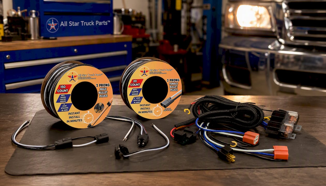
If you’re wiring clearance lights, start with the continuous marker light harness roll and its matching female bullet plug roll. Upgrading headlights, grab the H4 relay harness kit. Not sure which parts your specific panel needs, browse the full lighting and wiring catalog and match components to the diagrams in this guide. These are examples to build from, so always follow your local electrical code and the instructions that ship with your specific panel and components.
Authoritative Manuals and Standards to Consult
- VE Panel installation and service manual for panel-specific AC/DC separation and grounding rules
- DIN 72552 terminal identification for COM/L1/L2 labeling conventions
- Lutron switch installation instructions and Leviton switch installation instructions for terminal technique
- Reefer pre-trip inspection checklist for a model of the kind of pre-power inspection habit worth borrowing
Sources
- VE Panel installation and service manual (Victron Energy)
- Lutron multigang and switch installation instructions (PDF)
- Leviton switch installation instructions (PK-93713 PDF)
FAQ
How Do You Hook Up a Switch Panel?
Bring a fused positive feed to the panel’s input bus, tie all grounds to a single ground bus back at the battery, then run each switch’s COM terminal to that feed and its L1/L2 output to a fused leg feeding the load. Test each circuit individually before buttoning up the panel.
Which Wires Go Where on a Switch?
COM takes the incoming live feed, L1 and L2 carry the switched output to your load or to a second switch location in a traveler setup, and the green terminal always takes ground, following the labeling DIN 72552 documents. Never land a load wire on COM or a hot feed on L1/L2.
What Is the Correct Way to Wire an Electrical Panel?
Kill power and verify zero volts first, then plan and label every circuit before cutting wire. Bring in a fused main feed sized to the wire gauge, build a single ground bus, wire switches from COM to L1/L2, fuse every load leg near its source, and test each circuit before moving to the next.
How Do You Wire a Switch and Plug Combo With Two Wires?
A two-wire switch and plug combo typically carries hot on one wire through the switched half and a constant hot to the plug on the other, with ground handled separately as a third conductor in nearly every code-compliant setup. If your combo device only shows two conductors with no separate ground, confirm the manufacturer’s instructions rather than guessing, since combo devices vary in how they split switched and constant power.
Do I Need a Relay for High-Current Accessories?
Yes, for anything drawing more than a few amps, like headlights or a light bar, since running that current through a small toggle switch overheats the switch contacts over time. A relay lets the switch handle only the coil current while a separate fused feed carries the real load, which is exactly how an H4 relay harness kit is built.
Recommended
- 2 Pack- H8 H11 880 881 Female Adapter Wire Connector Replace OEM Headlight
- 12V LED Low Profile Submersible Rectangle Trailer Light Kit, Sealed Premium Waterproof
- 9007 9004 HB1 HB5 Socket High Temperature Ceramic Headlight Plug Pigtail
- Qty 2- H11 H8 H9 Wiring Harness Connector Extension Cable for Headlight
