


Trailer Light Wiring Diagram: 4–7 Pin Pinouts and Troubleshooting
White is ground, brown is tail, yellow is left turn and brake, green is right turn and brake, and blue is electric brakes. A 4-pin connector handles basic running, turn, and brake lights on smaller trailers. A 7-pin connector adds the blue brake circuit, a 12V auxiliary charge line, and reverse lights for trailers with electric brakes or onboard batteries. Jump to the pinout chart below for exact wire counts, or skip to troubleshooting if lights already aren’t working.
TL;DR:
- A 4-pin trailer connector only supports basic running, turn, and brake lights, while a 7-pin adds circuits for electric brakes, auxiliary power, and reverse lights.
- Proper wiring requires confirming wire functions and standards, especially for 7-pin connectors, to prevent damage from incorrect pin placement or incompatible standards.
- Using appropriate wire gauge and sealed, copper components minimizes voltage drops, corrosion, and electrical failures over time.
- Electric brakes need a dedicated 7-pin connector with a brake controller, and the blue wire must be properly wired to ensure full stopping power.
- Regular inspection, proper grounding, and the use of quality, waterproof components significantly reduce common trailer wiring issues.
Table of Contents
- Trailer Wiring Diagram and Color Chart by Connector Type
- How Do You Wire Each Trailer Connector Type?
- What Wire Gauge and Materials Should You Use?
- How Do You Wire Electric Brakes and Auxiliary Power?
- Which Installation Option Fits Your Trailer?
- How Do You Troubleshoot Trailer Light Problems?
- Sample Diagrams for Single-Axle and Tandem-Axle Trailers
- Why Component Quality Actually Matters in Trailer Wiring
- Trailer Light Kits and Wiring Products That Match These Jobs
- Sources
- FAQ
Trailer Wiring Diagram and Color Chart by Connector Type
Every trailer light wiring diagram follows the same backbone: white ground, brown tail, yellow left, green right. Those four wires show up on nearly every connector configuration sold in the U.S., from the smallest 4-pin flat to the full 7-pin RV blade. What changes as you move up in pin count is which extra circuits get added, and that’s where most people wire something wrong.
A 4-pin setup uses 18 to 14 AWG wire depending on the load each circuit carries, with white typically serving as the ground return. Add a 5th or 6th pin and you’re usually looking at a dedicated electric brake circuit (blue) plus a separate ground, or a combination that includes reverse lights. The 7-pin is where things get genuinely confusing, because there are two competing standards. The SAE 7-pin (traditional, found on most trucks) and the RV/blade 7-pin assign functions to different pin positions. Confirm which standard your vehicle and trailer actually use before wiring anything because plugging an SAE harness into an RV-style socket can send 12V straight into a circuit that expects a ground, and that blows fuses or fries a controller in seconds.
A few things worth memorizing before you touch a wire stripper:
- White and brown are the two wires you’ll find on literally every trailer connector made.
- Yellow (left) and green (right) carry both turn signal and brake light functions on most standard automotive wiring, since trailers typically don’t get separate brake lamps.
- Blue is reserved for electric brake controller output and only appears on connectors rated for brakes.
- Black or red typically carries 12V auxiliary power to charge a trailer battery or run accessories.
- Purple or gray, when present, usually runs reverse lights.
How Do You Wire Each Trailer Connector Type?
Before you start, gather a test light or multimeter, wire strippers, heat-shrink butt connectors, a heat gun or lighter for shrinking, dielectric grease, and an appropriately sized fuse or circuit breaker for any new circuit. Skipping the test light is how people end up chasing phantom shorts for an hour that a five-second continuity check would have caught.
Wiring a 4-pin flat connector:
- Identify the four wires on both the vehicle harness and the trailer harness. Viewing the connector face with the flat side down, pins typically run white (ground), brown (tail), yellow (left turn/brake), green (right turn/brake).
- Strip each wire about a half inch and match colors: white to white, brown to brown, yellow to yellow, green to green.
- Crimp with heat-shrink butt connectors rather than plain wire nuts. Trailers vibrate constantly, and a connection that isn’t mechanically locked will work loose within a season.
- Ground the white wire to bare metal frame, not just to another wire. A frame ground gives you a return path even if one splice fails down the line.
- Route the harness along the trailer frame using zip ties every 12 to 18 inches, keeping it away from the axle and any pinch points near the coupler.
Wiring a 5- or 6-pin connector follows the same color logic, but you’re adding either a reverse circuit or an electric brake and 12V feed. Confirm with a multimeter which pin carries which function before connecting, since manufacturers don’t always follow identical color codes once you get past the core four.
Wiring a 7-pin connector demands the SAE-vs-RV check mentioned earlier. Once confirmed, wire ground, tail, left, and right exactly as you would on a 4-pin. Then run blue to the brake controller output, black or red to a fused 12V aux feed from the battery, and purple or gray to the reverse light circuit. If your existing connector doesn’t have enough pins for what your trailer needs, that’s your sign to upgrade rather than force an adapter to do a job it wasn’t built for.
Pro Tip: Test every circuit with the trailer connected and before towing. A quick test-light check across each pin while a helper hits the brakes and blinkers catches a miswired brake circuit in your driveway instead of at a stoplight.
What Wire Gauge and Materials Should You Use?
Wire gauge matters more than most people assume, because trailer runs are long and voltage drop adds up fast over 15 or 20 feet of harness. Undersized wire on a brake circuit doesn’t just dim a light. It can cause a brake controller to underperform right when you need full stopping power.
- Tail and running lights: 18 to 14 AWG is plenty for the low current these draw.
- Turn and brake signal circuits: 14 AWG is the practical standard, since these see more frequent switching and slightly higher draw with LED clusters.
- Electric brakes and auxiliary power: 12 to 10 AWG, because brake magnets and battery charging pull real amperage over a sustained run.
On material, pure copper conducts better and resists corrosion longer than copper-clad aluminum (CCA). CCA is lighter and cheaper, and it’s fine for short, low-current runs like interior dome lights. For anything exposed to road spray, standing water at a boat ramp, or brake current, pure copper is the safer call. The tiny weight savings from CCA isn’t worth the added resistance and corrosion risk on a wire that has to work every single time you brake.
Sealing matters as much as gauge. Use adhesive-lined heat-shrink butt connectors at every splice, pack any open connector body with dielectric grease, and choose sealed, submersible-rated plugs wherever the connector sits low enough to catch water. Corrosion at connection points is consistently cited by service professionals as the leading cause of trailer electrical failure and is almost entirely preventable with a few dollars of grease and shrink tubing.
How Do You Wire Electric Brakes and Auxiliary Power?
The blue wire is the electric brake circuit, full stop. It carries a variable voltage signal from an in-cab brake controller to the magnets inside each brake drum, and that signal has to scale with how hard you’re pressing the brake pedal. A 4-pin connector has no wire allocated for this function. Electric brakes require a 7-pin connector at minimum, along with a dedicated brake controller wired into the vehicle, because the controller itself is what generates the variable signal the blue wire delivers.
Breakaway switch wiring is the safety backup for brake failure during a disconnect. The switch mounts near the coupler with a pull-pin cable attached to the tow vehicle. If the trailer separates unexpectedly, the pin yanks out and completes a circuit straight from the trailer’s onboard battery to the brake magnets, locking the wheels independent of the tow vehicle. Wire it through a fuse rated for the brake circuit’s draw, typically in the 20 to 30 amp range depending on axle count.
Auxiliary power routes 12V from the tow vehicle to the trailer battery, usually on the black or red wire. Best practice calls for 40A fused circuit protection on a constant aux feed, run through a relay or battery isolator so the trailer battery charges while driving but doesn’t slowly drain the tow vehicle’s battery when parked.
Common failure points on brake and aux circuits:
- Undersized fuses that blow under normal brake controller draw
- Corroded ground connections that cause intermittent or weak brake response
- Missing isolators that let a parked trailer drain the truck’s starting battery
- Breakaway batteries left uncharged for months, which fail exactly when needed
Which Installation Option Fits Your Trailer?
Three installation paths cover almost every situation, and picking the wrong one is how people end up re-doing a job twice.
- Custom vehicle-specific harness (T-connector): This plugs directly into your vehicle’s factory wiring without splicing anything. Manufacturers generally recommend this route whenever a factory-matched harness exists for your vehicle, since it’s the cleanest install and the easiest to troubleshoot later because every connection is a factory-made joint.
- Splice-in converter: For vehicles without a factory tow package, a splice-in converter taps into the existing brake and signal wiring behind the taillights. This works well but demands careful splicing, proper butt connectors, and a clear wiring diagram for your specific vehicle, since tapping the wrong wire can cause flickering dash lights or a blown fuse.
- Adapter (4-to-7 or similar): Adapters convert one connector type to another but only pass through the functions the smaller connector actually carries. A 4-to-7 adapter will not magically add brake or aux capability. If your trailer needs electric brakes and your truck only has a 4-pin, you need new wiring run to the brake controller, not an adapter.
Custom harnesses cost more upfront but pay off in reliability. Adapters are fine for occasionally towing a light utility trailer behind a car that will never need brake control.
How Do You Troubleshoot Trailer Light Problems?
Start with your eyes before you start with a meter. Most trailer lighting failures show visible evidence if you know where to look.
- Visual inspection: Check for cracked lens housings, visibly corroded pins in the connector, and any wire insulation that’s cracked or chewed near the axle.
- Ground check: A weak or corroded ground causes dim lights, lights that work on one side but not the other, or lights that flicker when the trailer bounces. Scrape the ground point to bare metal and retest.
- Fuse check: A blown fuse on either the vehicle or trailer side (if it has an onboard fuse block) will kill an entire circuit at once rather than causing a partial dim.
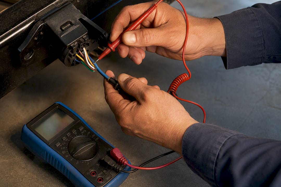
- Pin-by-pin function test: With the trailer connected, activate each function individually (running lights, left turn, right turn, brakes, reverse) while checking voltage at each pin with a test light or multimeter.
Corroded grounds and connector pins account for the overwhelming majority of trailer electrical complaints service shops see, and the fix is almost always the same: clean the contact, apply dielectric grease, and reseal with heat-shrink rather than leaving a bare splice exposed to road spray. A quick preventative routine of cleaning contacts and resealing connections cuts repeat electrical service calls significantly, which tells you most trailer wiring failures aren’t wiring failures at all. They’re maintenance failures.
To test a brake controller’s output, connect a multimeter to the blue wire at the connector and have someone press the brake pedal while the engine runs. Voltage should climb smoothly rather than jump erratically. For aux charging, check voltage at the trailer battery terminals with the engine running versus off. A properly wired and isolated system should show charging voltage only while the engine runs.
Pro Tip: Before disconnecting anything for a repair, snap a photo of the existing connections and label each wire with tape and a marker. It takes thirty seconds and saves you from staring at four identical white wires an hour later trying to remember which one went where.
Testing everything with a 12V test light in the driveway before you ever tow catches wiring mistakes on solid ground instead of at a boat ramp with your truck halfway in the water.
Sample Diagrams for Single-Axle and Tandem-Axle Trailers
A single-axle trailer’s wiring is about as simple as trailer electrical systems get. Ground runs to one frame point near the tongue, and tail, turn, and brake wires split at a single junction near the axle to reach each side’s light cluster.
| Circuit | Single-axle routing | Tandem-axle routing |
|---|---|---|
| Ground (white) | One frame ground near tongue | Frame ground near tongue plus a second ground at rear axle |
| Tail/running (brown) | Single run to both light clusters | Same run, tapped at both axle light clusters |
| Left/right turn-brake (yellow/green) | Splits once near the single axle | Splits at each axle; some installers parallel at one splice point instead |
| Electric brake (blue) | Runs to one set of brake magnets | Runs to a single splice point, then parallels to both axles’ magnets |
Tandem-axle trailers add complexity mainly around the brake and ground circuits. The brake controller’s blue output should parallel out to both axles from a single splice point rather than splitting the wire at each axle separately, which keeps resistance even across both sets of magnets. Ground points matter more here too. A single ground working double duty across a longer frame invites voltage drop, so a second ground point at the rear axle keeps the return path solid.
Before you disconnect anything on either layout, take photos of every existing connection and label wires with tape. It costs you a minute and saves an afternoon of guesswork when you’re halfway through a rewiring job and can’t remember which wire fed which light.
Why Component Quality Actually Matters in Trailer Wiring
Most trailer wiring failures trace back to one thing: cheap components that were never built to sit in road spray and salt for years. A wiring diagram only gets you a correct install on day one. What keeps that install working three years later is a sealed housing, a properly rated connector, and wire that doesn’t corrode from the inside out.
That’s the whole reason DOT FMVSS 108 compliance and submersible, IP-rated housings matter beyond just passing inspection. A connector that lets water in eventually corrodes regardless of how clean the wiring was on install day. Trucks and trailers running higher-quality, sealed components simply generate fewer service calls, because the failure points a shop sees most (corroded grounds, cracked housings, water-fouled connectors) get engineered out from the start.
— All
Trailer Light Kits and Wiring Products That Match These Jobs
If you’re wiring a basic utility trailer, upgrading a boat trailer for salt water, or replacing a cracked tail light housing, DOT-compliant kits built for exactly these jobs are available instead of generic parts that assume your trailer never sees water or road salt.
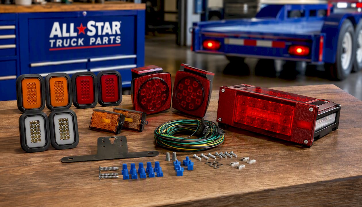
For a straightforward 4-pin install on a utility or single-axle trailer, the Trailer Wiring Harness Kit 4-Way Wishbone Style gives you pure copper, color-coded wire with a standard plug already terminated, so you’re matching colors instead of guessing pin functions. If you’re dealing with a boat trailer that spends real time underwater at the ramp, the 12V LED Trailer Light Wiring Kit is IP68 rated and built for exactly that submersion. For trailers needing a low-profile sealed setup with the harness already included, the 12V LED Low Profile Submersible Rectangle Trailer Light Kit comes with a 25 foot 4-pin harness and mounting bracket, cutting out a separate wiring purchase entirely. And if your current tail lights are cracked or fogged from age, the 5x3 Rectangle 42 LED Trailer Tail Light Kit meets FMVSS 108 standards with a submersible, grommet-mounted housing built for tow trucks and wide trailers alike. Check the specs and installation instructions on each product page before you order to confirm fit for your trailer’s width and axle count.
Sources
- Common trailer electrical problems and how to fix them
- RV standard electrical trailer wire colors
- Trailer Wiring Diagram: 4, 5, 6 & 7 Pin Connector Guide
FAQ
How Do You Wire a 4-Pin Trailer Light Connector?
Match white to white (ground), brown to brown (tail), yellow to yellow (left turn/brake), and green to green (right turn/brake), then secure each splice with a heat-shrink butt connector and ground the white wire to bare trailer frame.
What Color Wires Go Where on Trailer Lights?
White is ground, brown is tail/running lights, yellow is left turn and brake, green is right turn and brake, blue is electric brakes, black or red is auxiliary power, and purple or gray typically runs reverse lights.
How Do You Wire a 3-Wire Trailer Light?
A 3-wire trailer light setup typically uses ground, tail, and a combined stop/turn wire per side, so you’re wiring one side at a time with ground shared across the whole fixture rather than running four separate circuits.
How Do You Wire a 7-Pin Trailer Plug?
Confirm whether your vehicle uses the SAE or RV pin layout first, then wire ground, tail, left, and right as you would on a 4-pin, add blue to the brake controller output, black or red to a fused 12V aux line, and purple or gray to reverse.
Can a 4-Pin Connector Handle Electric Brakes?
No. A 4-pin connector has no circuit allocated for brake signal, so trailers with electric brakes need a 7-pin connector and a dedicated in-cab brake controller.
Recommended
- Trailer Wiring Harness Kit 4-Way Wishbone Style, Y Style 18AWG Pure Copper Core Color Coded Wire with Standard 4-Pin Flat Plug Connector
- 26 LED Magnetic Trailer Light Kit 2PCS LED Trailer Light Universal Running Brake Turn License Light
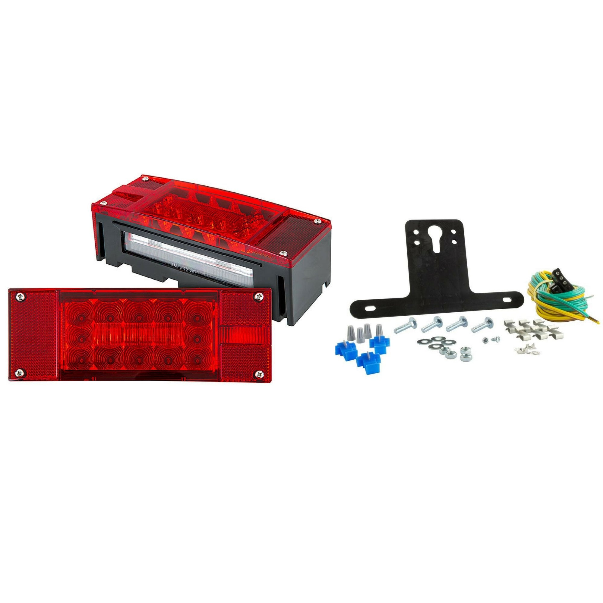
- 12V LED Low Profile Submersible Rectangle Trailer Light Kit Sealed Premium Waterproof Boat Trailer Stop Turn Tail License Plate Brake Running Lights
- 12V Waterproof Square LED Trailer Tail Light Kit Clear Lens Red Trailer Brake Stop Tail Turn Signal Running Lights License Kit
