


Diagram First Trailer Junction Box Wiring With Multimeter Tests
Wire the junction box by matching each verified vehicle socket function to its correctly labeled junction terminal, secure a dedicated low-resistance ground before touching anything else, and use the correct wire gauge for every circuit. Confirm each connection electrically with a multimeter rather than trusting wire color, and seal every entry point against moisture before closing the lid.
TL;DR:
- Verifying each vehicle socket pin with a multimeter prevents wiring misidentification that can cause circuit failures and blown fuses.
- Properly sizing the junction box to the total number of conductors ensures enough space for all wires, avoiding insulation damage and future faults.
- Correct grounding, achieved by cleaning metal surfaces and securing proper ring terminals, is essential to prevent flickering lights and erratic signals.
- Using the right wire gauge, especially for brakes and auxiliary feeds, minimizes voltage drop and reduces overheating risks over long runs.
- Sealing entry points and applying dielectric grease protect against moisture intrusion, which is the leading cause of junction box corrosion and failure.
Table of Contents
- What Does a Trailer Junction Box Actually Do?
- How Are 4-, 5-, 6-, and 7-Pin Connectors Wired?
- Wiring the Junction Box: The Actual Step-by-Step Process
- Getting the Ground Right and Wiring Brake Power
- What Wire Gauge and Fuse Do You Actually Need?
- Sealing the Junction Box Against Moisture and Corrosion
- How Do You Test and Troubleshoot Junction Box Wiring?
- How All Star Truck Parts Products Fit Each Wiring Task
- Why Do Junction Boxes Fail, and What’s Usually to Blame?
- How Trailer Lighting Functions Map to Your Wiring
- What Mistakes Cost People the Most Time on This Job?
- How Often Should You Inspect Junction Box Wiring?
- When to Wire It Yourself and When to Call a Pro
- Get the Parts That Match Every Step of This Job
- Sources
- FAQ
What Does a Trailer Junction Box Actually Do?
A trailer junction box is the central hub where the tow vehicle’s wiring harness meets every circuit on the trailer, including running lights, turn signals, brake lights, electric brakes, auxiliary 12V power, and sometimes a breakaway switch feed. Instead of splicing wires together loose under the frame where they corrode and fail within a season, you terminate everything at labeled screw or stud terminals inside a sealed enclosure. That single design choice is why junction boxes exist at all: they turn a tangle of butt splices into something you can actually diagnose six months later without cutting tape off ten different joints.
You need a box with enough terminals to match your connector type. A 4‑pin flat setup, which only handles running lights, left turn, right turn, and ground, gets by with four terminals. Step up to a 7‑pin round or blade connector, and you need terminals for ground, running lights, left turn/brake, right turn/brake, electric brake output, a 12V auxiliary feed, and sometimes a reverse circuit. According to Lippert’s trailer wiring guide, the 7‑pin setup is the standard whenever electric brakes or auxiliary power are involved, since a 4‑pin simply has no circuit to carry them.
Before you buy a box, count your actual conductors, not just your connector pins. A trailer with dual axle brakes, a breakaway switch, and interior lighting can easily need ten or more individual wire entries even on a “7‑pin” trailer, because some functions share a terminal while others branch to multiple lights. The box‑fill guidance from Chipmall’s junction box overview recommends sizing the enclosure to your total conductor volume, not just your pin count, so you’re not crushing wire insulation trying to close the lid.
Labeling matters more here than in almost any other part of trailer electrical work. A few habits that pay off later:
- Tag each wire with its function (not just its color) using a marker or printed label before you terminate it.
- Sketch a quick diagram of which terminal holds which function and tape it inside the box lid.
- Group brake and lighting circuits on opposite sides of the terminal block where the box allows it.
- Note the gauge of each conductor next to its label, since you’ll need that again if you ever add accessories.
That five-minute labeling step is the difference between a ten-minute fix next spring and pulling every wire to figure out which one went bad.
How Are 4-, 5-, 6-, and 7-Pin Connectors Wired?
Connector pinouts follow industry conventions, but the only way to know for certain is to test each pin electrically before you commit to a wiring plan. Color codes are a starting point, not a guarantee, since aftermarket harnesses and older vehicles sometimes deviate from the “standard” scheme.
The 4‑pin flat is the simplest connector and the one most limited in scope. It carries ground, tail/running lights, left turn/brake, and right turn/brake, and nothing else. There’s no circuit for electric brakes or a 12V feed, which is why the Wright Way Trailers connector guide points out that adapters letting a 4‑pin trailer plug into a 7‑pin vehicle socket only pass through the four functions the trailer side actually has. An adapter doesn’t create a brake circuit out of nothing.
The 5‑pin and 6‑pin connectors add a dedicated electric brake circuit and, in some configurations, a reverse light or auxiliary feed, depending on the manufacturer’s layout. The 7‑pin, whether round (RV-style) or blade (heavy-duty flat), is the connector you want when the trailer runs electric brakes, a breakaway switch, or powered accessories like a winch or interior lights.
The 7‑way wiring reference from Plug It Right is explicit on this point: color conventions exist across the industry, but they are not universal, and the only reliable confirmation is checking function at the socket with a meter or by referencing the vehicle-specific diagram.
Confirming orientation before you wire anything saves real time. Most round connectors have a keyway notch that only lets the plug seat one way, and molded plastic housings usually stamp small numbers or letters near each pin. If those markings are worn off or missing, here’s a quick sequence that works on any connector:
- Set your multimeter to DC voltage (20V range) and probe from each pin to a known ground while someone activates the corresponding function (brake pedal, turn signal, headlights).
- Note which pin lights up with which action, and write it down immediately, not from memory later.
- Cross-check against the vehicle’s own wiring diagram if one is available in the owner’s manual or service literature.
- Mark the confirmed pinout directly on the connector housing with a permanent marker so you never have to redo this test.
This sounds like overkill for a four-wire connector, but skipping it is exactly how people end up wiring a brake light to the turn signal circuit and burning out a bulb the first time someone signals and brakes at the same time.
Wiring the Junction Box: The Actual Step-by-Step Process
Getting from an open junction box to a sealed, tested, working circuit board comes down to five steps done in order. Skip the order and you’ll be redoing terminations after you’ve already closed things up.
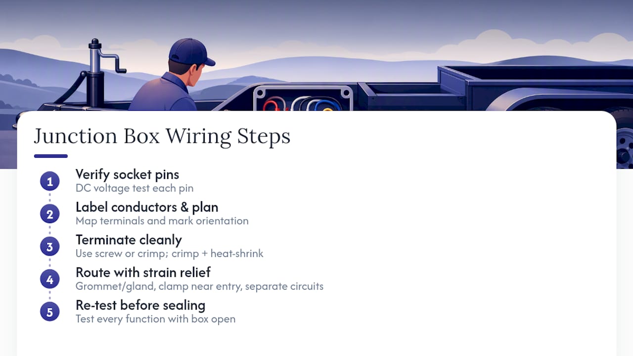
Step 1: Identify and verify every vehicle socket pin electrically. Don’t assume the vehicle harness matches any published diagram exactly, even if it’s supposed to be a standard 7‑pin. Using the DC voltage test from the connector section above, confirm which pin does what before a single trailer wire gets cut. This single habit, recommended in the Lippert towing guide, catches a surprising number of problems that people otherwise blame on bad trailer wiring when the real fault is a mislabeled vehicle socket or a blown fuse upstream.
Step 2: Label every conductor and plan your terminal layout before terminating anything. Lay out the box terminals and decide, on paper or with tape flags, exactly which wire lands where. A stepwise sequence, verify the vehicle side, identify the plug orientation, map to labeled terminals, then test each branch circuit, prevents the kind of guesswork that leads to a stripped wire landing on the wrong screw, a mistake the Otosection junction box diagram guide flags as one of the most common and most avoidable wiring errors.
Step 3: Choose your termination method and execute it cleanly. Junction boxes generally use one of two termination styles: a direct screw terminal that clamps a stripped wire end, or a stud terminal that takes a ring connector. For screw terminals, strip about 3/8 inch of insulation, twist the strands tight, and insert fully before tightening. For stud/ring terminals, crimp the ring connector onto stripped wire (about 1/4 inch of bare copper showing past the crimp barrel) and cover the crimp joint with adhesive-lined heat shrink. Crimping with a proper ratcheting crimper beats soldering for anything that will flex or vibrate, since solder joints get brittle and crack under constant road vibration. If you do solder, always add heat shrink over the joint afterward.
Step 4: Route wires with strain relief and physical separation. Every wire entering or leaving the box should pass through a grommet or cable gland, not through a bare drilled hole in the plastic or metal housing. Secure the harness with a cable clamp within a few inches of the entry point so vibration doesn’t work the wire loose from its terminal over time. Keep the electric brake circuit physically separated from the lighting circuits where the box layout allows, since a chafed brake wire touching a lighting wire can cause erratic behavior in both circuits at once.
Step 5: Re-test every circuit before you seal anything. With the box terminated but still open, run through each function again exactly as you did during vehicle-side verification. Confirm the tail lights, both turn/brake circuits, the electric brake output, and any auxiliary feed all read correctly at their assigned terminal. This is your last easy chance to fix a mistake. Once the lid is sealed and the grommets are compressed, pulling a wire back out means undoing weatherproofing you just finished.
Pro Tip: Take a photo of the finished terminal layout before you close the lid. Six months from now, when a light stops working, that photo saves you from reopening a fully sealed box just to remember which screw carries which function.
Getting the Ground Right and Wiring Brake Power
Test your ground connection before you troubleshoot anything else, because a compromised ground is the single most common root cause behind problems that look like they’re coming from three or four different circuits at once. When the return path back to the tow vehicle’s frame is weak or corroded, you get flickering lights, dim brakes, and erratic turn signals that all seem unrelated but trace back to one bad connection.
The diagnostic is simple: set your multimeter to continuity/resistance mode and measure from the trailer frame to the ground pin on the connector. A healthy ground should read low resistance, ideally around half an ohm or less. Anything meaningfully higher than that points to a bad connection somewhere in the return path, not a problem with the specific light or brake that’s acting up.
Many multi-circuit trailer failures that look like separate problems in the lights, brakes, and turn signals trace back to a single compromised ground path rather than three unrelated faults, which is why checking frame-to-pin resistance first, before chasing individual circuits, saves hours of misdiagnosis.
Attaching the ground correctly is a five-minute job that people still get wrong constantly:
- Sand or scrape the mounting point down to bare, shiny metal, not just visible metal under grime.
- Use a proper ring terminal sized to the ground wire’s gauge, never a wire wrapped around a bolt.
- Install a star washer or locking washer under the terminal to bite through any residual coating and maintain contact under vibration.
- Torque the bolt to snug plus a quarter turn; overtightening can crack a ring terminal’s crimp.
- Never use the hitch ball or coupler as your sole ground path. It carries mechanical load, gets greased regularly, and is not a reliable electrical return.
The 7‑way wiring diagram reference is direct on this last point: the ground has to carry the combined return current from every active circuit, so it needs to be sized and attached properly, not treated as an afterthought bolted wherever’s convenient.
Electric brake and breakaway battery circuits deserve their own dedicated feed, separate from the lighting circuits, protected by their own fuse. The breakaway battery, which fires the brakes if the trailer separates from the tow vehicle, should be mounted where it stays dry and accessible for periodic charge checks, and its feed wire should run at a gauge sized for the full brake current draw, not scaled down to match a lighting circuit nearby. Undersizing this one wire is a safety issue, not just a performance one.
What Wire Gauge and Fuse Do You Actually Need?
Wire gauge selection comes down to circuit type and run length, and getting it wrong in either direction causes real problems: too thin and you get voltage drop and overheating, too thick and you’re just wasting money and fighting a stiffer harness through tight grommets.
| Circuit Type | Recommended Gauge | Notes on Run Length |
|---|---|---|
| Marker/clearance lights | 18 AWG | Fine for short branch runs |
| Tail/running/turn/brake lights | 16 AWG | Standard for most trailer lengths up to 25 feet |
| Electric brakes | 14 AWG or 12 AWG | Use 12 AWG on tandem-axle setups or runs over 25 feet |
| 12V auxiliary/accessory feed | 10 AWG to 14 AWG | Size to the actual accessory draw, not a guess |
| Ground/return | Match or exceed largest feed circuit | Undersized ground defeats every other correct gauge choice |
Fuse sizing follows a rule that trips up a lot of first-time wiring jobs: the fuse protects the wire, not the device on the other end of it. If you run 16 AWG wire rated for roughly 10 amps continuous, you fuse that circuit at 10 amps or less, regardless of what the light bulb or brake magnet actually draws. A common electric brake circuit pulling around 3 to 4 amps per axle magnet still gets fused based on the wire’s ampacity if it shares a feed with other loads, not based on the magnet’s draw alone. If the fuse is sized to the device instead of the wire, a short circuit can push current well past what the wire can handle before the fuse ever blows.
Conductor material matters as much as gauge. Pure copper wire carries more current at a given gauge than copper-clad aluminum (CCA), resists corrosion better at connection points, and doesn’t work-harden and crack the way CCA does under repeated flexing. CCA wire is cheaper, which is exactly why it shows up in bargain harness kits, but the connection failures it causes over a few seasons of vibration and moisture exposure usually cost more in diagnostic time than the wire saved in sticker price.
Sealing the Junction Box Against Moisture and Corrosion
A junction box with perfect wiring inside still fails if water gets in, since corrosion at a terminal produces exactly the same symptoms as a bad connection, just slower and harder to spot until it’s advanced.
Start with box orientation. Mount the junction box with cable entries facing downward or to the side, never straight up, so water beads and rolls off instead of pooling against a seam. If the box has a gasketed lid, check that the gasket seats evenly all the way around before you tighten the screws; a gasket pinched unevenly on one corner leaves a gap on the opposite side that you won’t notice until the next rainstorm.
Every wire entry point needs a grommet or cable gland sized snugly to the harness diameter, not a hole drilled slightly big “to make it easier to feed through.” That extra clearance is exactly where water gets in. Add a cable clamp or zip tie just outside the grommet so the harness can’t work back and forth against the seal every time the trailer bounces over a pothole. Where you have spliced connections inside or near the box, adhesive-lined heat-shrink tubing beats plain electrical tape every time, since the adhesive flows into the joint and seals it rather than just wrapping around the outside.
- Choose a box material rated for the trailer’s actual exposure (open boat trailer versus enclosed cargo trailer have different needs).
- Apply dielectric grease to every terminal connection before closing the lid.
- Use stainless steel screws and hardware on the box itself to avoid rust seizing the lid shut later.
- Inspect the box every few months, more often if the trailer sees saltwater boat launches or winter road salt.
Sealed lights and sealed harness kits reduce how many intrusion points you’re managing in the first place, since fewer connections outside the box means fewer places for water to find a way in.
Pro Tip: A thin film of dielectric grease on a terminal doesn’t stop electrical contact, it stops oxygen and moisture from reaching the metal. Apply it after you tighten the connection, not before, or you risk it interfering with a clean crimp or screw contact.
How Do You Test and Troubleshoot Junction Box Wiring?
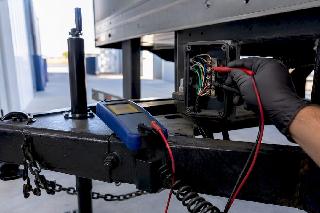
A multimeter and a clear sequence solve the overwhelming majority of trailer wiring faults without ever pulling the box apart blind. Set your meter to DC voltage on the 20V range for live circuit checks, and to continuity or resistance (Ω) mode for ground and conductor integrity checks.
- Test the ground first. Measure resistance from the trailer frame to the ground terminal. A reading below roughly 0.5 ohms is healthy; anything higher, or a reading of “O.L” (open loop, meaning no continuity at all), means you have a broken or corroded ground path before you even look at another circuit.
- Check voltage at the vehicle socket before connecting the trailer. With the tow vehicle running and lights/turns/brakes activated one at a time, confirm each pin reads roughly 12.6 to 14.4 volts, matching the healthy range noted in EngineerSkill’s multimeter testing guide. A pin reading 0V when it should be active points to a blown fuse or bad wire on the vehicle side, not the trailer.
- Test each junction box terminal live, one function at a time. A steady voltage in the expected range means that branch is good. A reading that pulses or drops sharply under load usually means a corroded connection or undersized wire struggling to carry current. A dead 0V reading traces back through the harness toward the vehicle connector.
- Test without a tow vehicle using a charged 12V battery. Touch the positive lead to the appropriate pin and the negative to a confirmed good ground, and watch which trailer function activates. This isolates trailer-side wiring completely from any vehicle-side fuse or wiring questions.
- Match the symptom to the likely cause. Green or white crust at a terminal means corrosion, usually from a compromised seal, and the fix is cleaning the contact and resealing. A light that works when you jiggle the harness but not otherwise means a loose screw terminal or a partially broken conductor inside the insulation, and the fix is re-terminating that wire, not just tightening what’s already there.
A blown fuse or a corroded vehicle-side socket causes more “trailer wiring failures” than actual trailer wiring does. The Lippert wiring guide makes this point directly: check vehicle-side voltage before you cut a single trailer wire, since a lot of “bad trailer wiring” diagnoses turn out to be a $3 fuse or a dirty vehicle connector.
Common failure patterns worth recognizing on sight: a light that’s dim but not dead almost always means voltage drop from either an undersized wire or a corroded connection point upstream. A circuit that works intermittently, especially over bumps, usually means a wire that’s mechanically loose at its terminal rather than electrically damaged. A circuit that’s completely dead, confirmed by an O.L reading on continuity, means a full break somewhere in that specific run, and tracing it segment by segment from the junction box outward toward the light is faster than guessing.
How All Star Truck Parts Products Fit Each Wiring Task
Matching the right part to the specific job in your junction box saves you from over-buying or, worse, under-building a circuit that fails again in a year.
If you’re replacing worn or fogged submersible lights, the 5x3 rectangle 42 LED trailer tail light kit is built to DOT FMVSS 108 and SAE I6 P2 standards, with included grommets and plugs designed for direct connection into your junction box’s stop, turn, tail, and park terminals. It’s a straightforward swap when you’re replacing failed lamps rather than rewiring from scratch.
For a new build or a full harness replacement where you want to minimize the number of connection points feeding your junction box, the 12V LED low-profile submersible light kit comes with its own 25-foot 4‑pin wiring harness and mounting bracket already sealed, which means one weatherproof entry point into the box instead of several separate light leads you have to seal individually.
When you’re doing multiple marker or clearance light splices along a trailer’s length, the 18G double-female bullet plug connector roll speeds up the repetitive work considerably.
All three products share the same underlying design philosophy behind Allstartruckparts: leak-proof housings, thicker copper conductors than typical budget alternatives, and construction built to exceed DOT standards rather than just meet the minimum. For a junction box job where every connection point is a potential failure point down the road, that margin matters more than it looks like on a spec sheet.
Why Do Junction Boxes Fail, and What’s Usually to Blame?
Corrosion and bad grounds cause the overwhelming majority of junction box complaints, and they’re often mistaken for each other or for something more complicated. Green or white buildup on a terminal is straightforward: moisture got past a seal, reacted with the metal, and now the connection has resistance where it should have none. The fix is cleaning the terminal back to bare metal, re-terminating with a fresh connection, and fixing whatever let water in to begin with, usually a missing grommet or a gasket that wasn’t seated correctly.
A bad ground shows up differently and gets misdiagnosed more often, because it doesn’t look like one problem. It looks like flickering lights on one side, dim brakes, and a turn signal that only sort of works, all at once. People chase three separate repairs before realizing the frame-to-ground connection itself has failed. That’s exactly why testing ground resistance first, before touching any individual circuit, catches this pattern immediately instead of after three wasted repair attempts.
Loose screw terminals are the third repeat offender. Vibration works fasteners loose over months of driving, and a connection that was solid at installation slowly degrades until a light starts flickering over bumps. Checking terminal tightness during routine inspection catches this before it becomes an intermittent no-power complaint that’s much harder to trace.
Mismatched connectors round out the list. Running a 4‑pin trailer through an adapter to a 7‑pin vehicle socket doesn’t create an electric brake circuit that wasn’t there, and trying to force one through an adapter’s spare pin is a common way to fry a fuse or a control module.
How Trailer Lighting Functions Map to Your Wiring
Every function on a trailer connector corresponds to a specific behavior you can observe and test, which makes troubleshooting far more concrete than it sounds.
Running lights (sometimes called tail or marker lights) stay on continuously whenever the tow vehicle’s headlights or parking lights are active, and they wire to a single dedicated circuit that runs to every marker and tail light on the trailer. Turn signals are a separate circuit on each side, left and right, that flash only when that turn signal is activated, and they typically share a wire with the brake light function on that same side, a design called “combined stop/turn.”
Brake lights illuminate on both sides simultaneously when the tow vehicle’s brake pedal is pressed, riding the same physical wire as the turn signal on each side but activating differently, steady on braking, flashing on turning, which is why a bulb or wire fault on that circuit often shows up as a problem with both functions at once. Electric brakes are a completely separate, higher-current circuit that sends a variable voltage signal to the trailer’s brake magnets, proportional to how hard the tow vehicle’s controller applies them; this circuit has nothing to do with the brake lights despite the shared name.
The auxiliary 12V feed powers accessories unrelated to lighting or braking, interior lights, a winch, a battery charger, and it draws continuously whenever the vehicle’s ignition or accessory circuit is active, not tied to any specific action like braking or signaling.
What Mistakes Cost People the Most Time on This Job?
Wiring by color alone without verifying function electrically is the single most repeated mistake in trailer wiring, and it’s avoidable in under five minutes with a multimeter. Aftermarket harnesses, older vehicles, and previous owners’ “creative fixes” all introduce color deviations from the standard scheme, and assuming brown always means tail light leads directly to a wired brake light circuit acting like a turn signal.
Skipping strain relief is the second big one. A wire terminated perfectly but left to flex freely at the entry point will eventually work itself loose or chafe through its insulation against a metal edge. The fix costs a couple of dollars in cable clamps and takes two extra minutes; skipping it costs you reopening a sealed box six months later.
Undersizing the ground wire relative to the load it carries is a mistake that doesn’t show up immediately, which is exactly why it’s dangerous. Everything works fine on day one, then starts flickering and dimming as connections season and resistance creeps up over months of vibration and moisture exposure.
Using electrical tape instead of adhesive-lined heat shrink on splices is a shortcut that looks fine for the first rainstorm and fails by the third. Plain tape’s adhesive degrades with heat and UV exposure and stops sealing long before the wire underneath actually fails.
Finally, closing the box before fully re-testing every circuit means any mistake you made during termination gets discovered later, usually on the side of the road, instead of in your driveway with tools already in hand.
How Often Should You Inspect Junction Box Wiring?
A quick visual and functional check every three to four months catches most developing problems before they become a roadside failure, and it takes less time than filling a fuel tank. Open the box, check for any moisture, corrosion, or discoloration at terminals, and confirm each screw or stud connection is still tight.
Test every lighting and brake function with a helper or a set of trailer-side testers before any trip longer than a quick local haul, especially after the trailer has sat unused for a season. Connections that were solid in the fall can develop resistance over a winter of temperature swings and humidity, even without any visible damage.
Reapply dielectric grease to terminals roughly once a year, or sooner if the trailer regularly sees saltwater, road salt, or heavy rain exposure. It’s a cheap habit that meaningfully extends how long connections stay corrosion-free. Replace any gasket that’s cracked, flattened, or no longer seating evenly around the lid, since a degraded gasket is invisible until water gets past it.
Keep a simple log, even just a note on your phone, of when you last inspected the box and what you found. Patterns matter here: a terminal that keeps showing early corrosion signs might point to a grommet that’s slightly undersized or a box orientation that’s collecting water it shouldn’t.
When to Wire It Yourself and When to Call a Pro
Basic lighting circuits, a 4‑pin or 5‑pin setup, and straightforward junction box terminations are well within reach for most DIY trailer owners with a multimeter and some patience. Before you start, disconnect the trailer from any power source, support it securely so it can’t roll or shift while you’re underneath it, and wear safety glasses when crimping or cutting wire.
Hand it to a professional when electric brake wiring involves a controller you’re not confident diagnosing, when you’re unsure about box-fill code requirements for a commercial trailer, or when you’ve found a safety-critical fault, corroded brake magnet wiring, a compromised frame ground on a heavy trailer, that you can’t fully resolve with basic testing. Getting a brake circuit wrong isn’t like a dim marker light; it’s a stopping-distance problem.
Whatever route you take, reference actual product specs and wiring diagrams before buying parts, and don’t hesitate to ask a specific technical question before you order anything. A five-minute question up front beats returning a part that didn’t match your circuit.
— All
Get the Parts That Match Every Step of This Job
The parts described in this guide include leak-proof housings, thicker copper conductors, and hardware designed to meet or exceed relevant DOT standards, helping ensure durable and reliable connections.
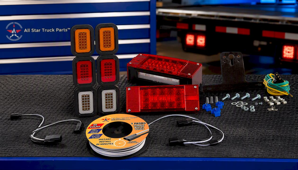
If you’re replacing lamps that have fogged or failed, the 5x3 rectangle 42 LED tail light kit drops into a junction box’s stop, turn, and tail terminals with grommets already included. Building a cleaner main harness entry into a sealed box gets easier with the submersible light kit and 25-foot harness, which cuts down on separate entry points to seal individually. And if you’ve got a run of marker lights to splice, the 18G bullet plug connector roll makes quick, reliable work of connections that would otherwise eat an afternoon.
Browse the full lighting and wiring catalog to match parts to your specific trailer setup, or reach out to the support team with your connector type and circuit list before you order, so you get the right gauge and connector count the first time.
Sources
The wiring specifics above draw on a handful of technical references worth bookmarking if you’re doing this job regularly.
- Engineerskill
- 7-Way trailer wiring diagram with brakes - Plug It Right
- Ultimate trailer wiring guide - Lippert
FAQ
Are all 7‑pin trailer connectors wired the same way?
No. While most 7‑pin connectors carry the same core functions, ground, running lights, turn/brake signals, electric brake, and a 12V auxiliary feed, color assignments and exact pin positions vary by manufacturer. Always verify each pin’s function electrically with a multimeter rather than assuming color matches a standard chart.
How is a 3‑wire junction box wired?
A 3‑wire junction box typically handles ground, running lights, and a combined brake/turn function on a single side or a shared circuit, common on smaller utility trailers with basic lighting. Match each incoming vehicle wire to its verified function before terminating, and confirm the ground reads low resistance to the frame before testing the other two circuits.
What is a 7‑way trailer plug with a junction box?
A 7‑way plug with a junction box is a wiring setup where the vehicle-side 7‑pin connector feeds into a sealed enclosure on the trailer that distributes each of the seven functions, ground, lights, turns, brakes, electric brake, and auxiliary power, to labeled terminals. This setup makes it much easier to troubleshoot or add circuits later compared to loose splices under the frame.
How do you wire a junction box correctly?
Wire it by first verifying every vehicle socket pin’s function with a multimeter, then labeling each conductor and mapping it to the correct terminal before terminating anything. Secure a low-resistance ground first, use the appropriate gauge for each circuit, and re-test every function before sealing the box against moisture.
What causes most trailer junction box failures?
Corrosion from moisture intrusion and a compromised ground connection cause the large majority of junction box problems, often producing symptoms across several circuits at once rather than one obvious failure. Checking ground resistance first and keeping every wire entry properly sealed with grommets prevents most of these issues before they start.
Recommended
- Trailer Wiring Harness Kit 4-Way Wishbone Style, Y Style 18AWG Pure Copper Core Color Coded Wire
- Heavy Duty 14 Gauge 4 Way Conductor Wire RV Trailer Cable Cord Insulated Stranded Pure Copper
- 7 Way Trailer Wire 14 Gauge – CCA Conductor Cable (30% Copper CCA)
- Heavy Duty 14 Gauge 4 Way CCA Conductor Wire RV Trailer Cable Cord Insulated Stranded Copper Clad Aluminum
